Plenty Global
Pumps can be used as:
and many more to give just a few examples.
The pumps are available as / with:
Available materials for the pump casings or components:
The following engines are possible:
Professional pump users have a variety of pump technologies available for a wide variety of industries and uses. Whether for ash disposal, autoclave feeding, spray drying, dosing, extraction, descaling, cooling, industrial cleaning of surfaces and components or for many other uses - at SPA you will find the right pump for your application.
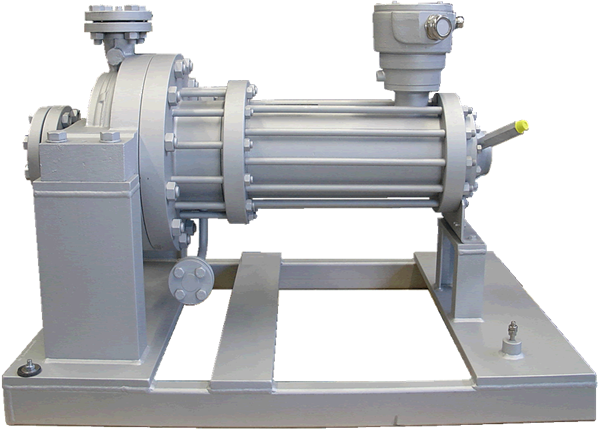
1- Canned motor pumpsThe canned motor pump is an integral, compact unit without shaft seal. This type of pump combines the rotating part of the pump hydraulics with the rotating part of the motor on a common shaft. The pump shaft is completely enclosed by a tightly welded rotor lining that separates the rotor assembly from the stator of the drive motor. This design principle eliminates the need for shaft seals (e.g. mechanical seals or shaft bushings) and prevents leakage. Therefore, canned motor pumps are also called 'sealless' or 'hermetically sealed'.
Technical features of canned motor pumps
Canned motor pump technology is often used when critical media (toxic or carcinogenic) must be conveyed or when extreme operating parameters (e.g. low-temperature applications down to -160 °C, high-pressure pumps up to 1200 bar system pressure, high-temperature versions for pumped media of up to 450 °C) need to be implemented.
The reason: In addition to the motor can as a hermetically sealed component, the special, pressure-resistant motor housing represents a second safety containment that reliably prevents the pumped medium from leaking into the environment even in case of an accident. For this reason, liquid gases with high vapor pressures that otherwise require complex shaft seal systems are a typical application for canned motor pump technology.
Benefits of canned motor pumps
different versions possible:
different types of installation possible:
Range of typical applications for canned motor pumps

2- Centrifugal Plastic Pumps
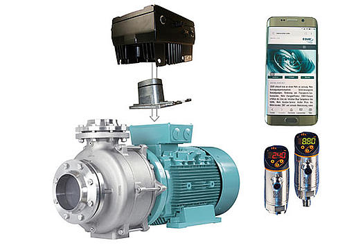
Plastic Pumps, also called Non-Metallic Pumps, are mostely Centrifugal Pumps based on the radial pump technology. In a centrifugal plastic pump all parts in contact with the fluid are from solid plastic. This is what makes plastic centrifugal pumps a perfect match if it comes to corrosive and abrasive fluids. Moreover, centrifugal plastic pumps do comply with common standards and they do meet high demands for safety and reliability that are common in industrial processes.
Like in any other centrifugal pump the liquid entering the pump casing is being accelerated by the rotating impeller. At the discharge of a volute casing speed is being converted into pressure. Impeller and volute casing have to match each other to create the best efficient hydraulic unit of the pump. The larger the impeller diameter and speed are, the larger the pressure difference will be and the wider the impeller and volute are the higher the flow of the pump will be.
Most pumps are driven by electric motors. This is not at all different with plastic pumps. The energy a pump requires has a linear increase with pressure and flow. The motor transmits the energy through the pump shaft to the impeller but not all of it is converted into pressure. Energy losses are created by friction on bearings and hydraulic imperfections such as vortexes and backflow. Manufacturers of high quality pumps put considerable efforts into hydraulic R&D in order to minimize these losses. Today those HQ plastic pumps achieve efficiencies up to 80%.
Technical Data of Centrifugal Plastic Pumps
| Flow Rate | up to 3.000 m³/h (13.200 gpm) |
| Delivery Head | up to 100 m (330 ft) |
| Operating Pressure | up to 16 bar |
| Operating Temperature | up to 180°C (356°F) |
| Viscosity | up to 300 mm²/s |
Applications where Plastic Pumps are unconquerable
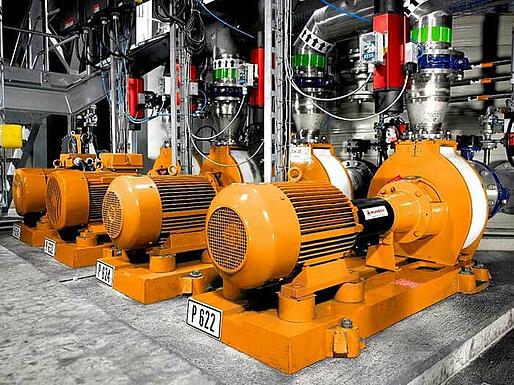
3- Radial flow pumps
The biggest subsection of the centrifugal pumps is the radial pump. The handled liquid is exiting the impeller radially. The achieved delivery head is proportional to the impeller diameter. To realize higher heads, several impellers are put in series (multistage pumps), where guide rings lead the handled medium from radial flow to the axial inlet of the next stage.
Radial flow pumps are centrifugal pumps in which the fluid is pumped perpendicularly to the pump shaft.
The flow mechanism in a centrifugal pump can generally be described as follows: Through a suction flange the liquid flows through the suction hub into the rotating impeller due to an energy fall. The pump unit absorbs mechanical energy from a drive motor through a shaft. The blades of the impeller which is permanently fixed on the shaft exert a force on the fluid and increase its angular moment. Pressure and absolute speed increase as a result. Consequently energy is being transferred to the fluid. The energy which is present in kinetic form as an increased absolute speed is usually converted into additional static pressure energy by a diffuser device. Nowadays volute casings or bladed diffusors normally are being used as diffuser devices. In combination with the impeller the diffuser device represents the so-called hydraulic of the pump. To maintain the flow there also has to be an energy fall directly behind the pump after the outlet from the discharge flange, analogous to the pump inlet. Losses occurring in the system for example due to friction or leakage flows require an increased power consumption of the pump.
Centrifugal pumps differ in their constructive and functional characteristics due to their pre-determined installation location and the liquid to be pumped. For pumps of one model range various installation types may be implemented. The hydraulic characteristics and the pumping performance remain nearly unchanged. Main characteristics are the design of the shaft in the horizontal or vertical position, the position of the pump connections and the connection type of the pump to the drive unit using a coupling or direct assembly on the motor shaft (block design).
Technical features of a radial pump
Benefits of a radial pump
Range of applications of a radial pump
Delivery characteristics of a radial pump
| Delivery output | up to 3000 m³/h |
| Delivery height | up to approx. 1200 m |
| Rotary speed | 2,900/1,450 (50 Hz) and 3,500/1,750 (60 Hz) (feste Geschwindigkeit), use of frequency controller easily possible |
| Solids content | up to max. 30 % and up to a max. grain size of 80 mm |
| Gas content | up to max. 30 % |
| Operating pressure | up to max. 1200 bar |
4- Side channel pump
A niche product between displacement pump and centrifugal pump
Side Channel Pumps fill the hydraulic performance void between the positive displacement pump and centrifugal pumps.Side Channel Pumps are used for low flow and high head applications. They handle fluids with gas entrainment of up to 50% and are ideal for handling volatile, high vapor pressure fluids with low viscosities.
Fully open "star" impellers interact with the side channel casing creating an intense transfer of energy to the pumped liquied or fluid/gas mixture. The corresponding pressure increase ( pump head ) equals 5-10 times the amount generated by a similar size centrifugal pump at the same RPM.
Side Channel Pumps are used for these typical liquids:
Characteristics of a side channel pump
Side Channel Pumps are multi stage pumps of a systeme-kit with 6 sizes and max. nine stages with or without shaft sealing and an additional suction stage to reach extremely low NPSH values.Various materials are available like cast iron, ductile iron, bronze, chrome steel and stainless steel
Delivery characteristics of a side channel pump
Benefits of a side channel pump
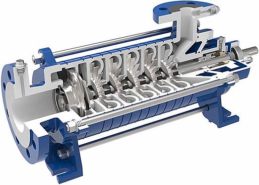

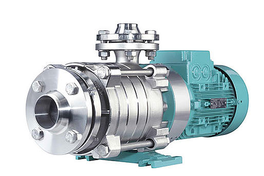
5- Regenerative turbine pump
Suitable for small flow rates and high discharge pressures.
Regenerative turbine pumps are centrifugal pumps for pumping pure liquids. They are used where great delivery heads are required with small volume flows. Furthermore, by contrast with other centrifugal pumps, regenerative turbine pumps are capable of also handling large gas proportions without interrupting the liquid stream.
With regenerative turbine pumps, which have to be assigned to centrifugal pumps, energy transmission to the pumped liquid takes place in the impeller and the surrounding side-channel. Due to centrifugal forces, the pumped liquid circulates several times out of the side-channel back into the impeller. That way, energy transmission is increased and large delivery heads can be achieved despite a small construction size. The general functional principle is similar to the one of side-channel pumps. The difference is that the side-channel of a regenerative turbine pump also stretches along the end face of the impeller.
Regenerative turbine pumps often have more than 20 shovels which are arranged in a star shape on both sides of a support disc.
Benefits of a regenerative turbine pump
In case of proportionate outgassing of the medium or short-term air entry, peripheral pumps can operate without the flow rate tearing off. In addition, very large gas proportions can be permanently co-conveyed. They are particularly suitable with multiphase applications with low volume flows.
Range of applications of a regenerative turbine pump
Regenerative turbine pumps are used where great delivery heads with small capacities and pumps with small dimensions are required. They are suitable for pure, non-abrasive or polluted pumped liquids.
Regenerative turbine pumps are used, for instance, in car wash installations, to increase pressure in water networks, in the chemical industry or in mechanical engineering for cooling, recirculation and as small boiler feed pump.
Besides, they are used for enrichment and mixture of liquids with gases. Main application fields in the multiphase range are biofuel plans, dissolved air flotation DAF, neutralisation, drinking water treatment, bioreactors, crude oil water separation on oil rigs and oilfields as well as general process technology.
Delivery characteristics of a regenerative turbine pump
| Working range | Q= 0.5 - 15 m³/h |
| Maximum delivery head | 107 m (50 Hz); 145 m (60 Hz) |
| Temperature | PBU: 80°C to 140°C PBM: up to 200°C |
| Working pressure | PBU / PBM: max. 16 bar |
| Viscosity | up to 1E-3 Pas |
| Gas content | up to 15% |
| Ambient temperature | -20°C up to 40°C |
Technical features of a regenerative turbine pump
1- Dosing pump
For maximum metering accuracy and reliability
This description is given by the reciprocating movement of the displacer, in the form of a plunger or a diaphragm, which alternately increases and decreases the working space. In order to prevent return flow of the conveyed medium, the working space has to be closed by two valves.
During the backward movement of the displacer, the working space increases and a vacuum is formed relative to the pressure in front of the automatic suction valve. Due to this pressure difference, the suction valve opens and the conveyed fluid is sucked into the working space. Once the displacer reaches its rear dead-center position, the suction stroke ends. The suction valve closes by its own weight or by an additional spring load. During the forward movement of the displacer, the working space decreases. As a result, the pressure increases. When the pressure increases to slightly above the discharge pressure, the automatic discharge valve opens and the fluid volume is now discharged from the working space. In the front dead-center position, the pressure valve closes. Then the next stroke cycle begins.
In most reciprocating positive displacement pump designs, the flow rate depends only minimally on the discharge pressure. This entails a rigid pressure characteristic curve. Furthermore, the flow rate has a linear dependency on the stroke length and stroke frequency. Reciprocating positive displacement pumps are therefore suited to the conveyance and precise metering of fluids across a wide pressure and flow rate range.
The leak-free variants, i.e. hermetically sealed diaphragm pumps, enormously expand the range of application of the oscillating positive displacement pumps so that the fluids can have the following properties:
Benefits of a dosing pump / Advantages:
Delivery characteristics of a dosing pump
2- Gear pump
Ideal to transport different media
The external gear pump belongs to the class of rotating postive displacement pumps. They can manage low viscosity liquids like alcohols, solvents or liquid gases as well as medium and high viscosity liquids like polymer melts, gumbase or rubber. Liquids containing solids are not really suitable for gearpumps unless the particles are really small.
A gear pump comprises a housing with two covers. The powered gear wheel and driven gear wheel are borne in four friction bearings. The protruding drive shaft is sealed. The meshing gear wheels are enclosed by the housing. The amount of clearances between the tips of the teeth and the housing is extremely small and precisely defined There are ports in the housing. One port is at the suction side (inlet) and the other at the pressure side of the pump (discharge). One gear wheel is normally driven by a motor connected to the drive shaft, which protrudes from the housing. When the gear wheels are rotating, a chamber, which is filled with the medium being pumped, is formed between two teeth and the housing. The medium is thus conveyed from the suction side to the pressure side of the pump. The medium being pumped is displaced from between the gap between the teeth at the point at which the teeth mesh. For this reason, the gear pump is known as a displacement pump.
Benefits of a gear pump
External gear pumps are used preferably for liquids that do not contain any solids. The viscosity range is between 0,2 mPas and 1 Million mPas. The liquid should have lubricating properties.
Delivery characteristics of a gear pump
Technical features of a gear pump
3- Multi screw pump
Unrivaled lubrication pump, but also with high potential for many other applications
Multi screw pumps belong to the group of self-priming, valve-less rotating positive displacement pumps. Due to their design they are specially suitable for lubricating media. Although they are compact in design they can reach high flow rates and high pressure. Some designs are even suitable for non-lubricating or solid loaden fluids.
Functioning of a multi screw pump
The delivery principle is based on a drive spindle transferring torque through a thin hydrodynamic film to the rotating intermeshing one or two driven spindles.
Designs that are suitable for non-lubricating media or handling solids, need a timing gear to synchronize the spindles.
The rotation of the screw creates chambers what will moved continously from the suction to the discharge side and create a negative suction pressure and the media will be drawn in.
The matching design of housing and screws hydraulically balances against high radial and axial loads to guarantee a long service ife of the pump.
Various housing designs make the pumps suitable for all installation situations.
Delivery characteristics of a multi screw pump
Flow rate and pressure are depending on pump size, geometry and number of screws and have to be defined depending on medium and application.
Range of applications of a multi screw pump
Technical features of a multi screw pump
Benefits of a multi screw pump
4- Piston diaphragm pump
Wherever abrasive, aggressive and toxic fluids and slurries are conveyed, hermetically sealed, oscillating displacement pumps are used. Even for extreme operating temperatures and heterogeneous mixtures with high solids content, piston diaphragm pumps turn out to be the best pump technology for numerous applications. The advanced, unique, patented MULTISAFE® technology with the hermetically sealed, redundant double hose-diaphragm system guarantees a doubly secured transport of critical and environmentally hazardous fluids.
Functioning of a piston diaphragm pump
Piston diaphragm pumps are oscillating positive displacement pumps, whose diaphragms are actuated by an oscillating piston or plunger via a hydraulic liquid. During the backward movement of the piston or plunger (suction stroke), liquid flows into the pump chamber through the open suction valve. The forward movement of the piston or plunger (discharge stroke) fully activates the diaphragm. The subsequent pressure increase closes the suction valve, opens the discharge valve and the fluid is transported out of the pump chamber.
The double hose-diaphragm pump as a consistent further development of the piston diaphragm pump is a hermetically sealed, leak-proof, oscillating displacement pump with double sealing of the wet end from the hydraulic drive end and the environment by means of two hose-diaphragms, which are arranged one inside the other. The liquid is conveyed through the pump in a linear flow path, fully enclosed by the hose-diaphragms ensuring that the liquid is in contact with the hose-diaphragm and the check valves only. Hence, erosion and corrosion are minimized to the maximum possible extend.
Technical features of a piston diaphragm pump
Range of applications of a piston diaphragm pump
Benefits of a piston diaphragm pump
5- Progressing cavity pump
Gentle dosing of solid-loaden media – even at high pressures and viscosities
Progressing cavity pumps belong to the group of rotating positive displacement pumps. They are self-priming, valve-less, and due to their high process liability and suction capacity they are often used for the continuous, gentle conveyance and precise dosing - in proportion to speed - of difficult media.
Functioning of a progressing cavity pump
The delivery principle is based on a rotor which turns in an oscillating motion within a fixed stator. The coordinated, spiral geometry of both components creates delivery chambers in which the medium is transported from the suction to the pressure side. Due to the design of rotor and stator, hardly any pulsation or shearing forces are effecting the fluid. Instead, the medium is transported gently and continuously.
Consistency and especially the viscosity are not a factor for the delivered flow with this displacement technology; the transported quantity is determined by the speed alone and – in combination with a frequency inverter – can be regulated conveniently and with precision. This enables an accuracy of between five and three percent to be achieved; small dis-pensers even achieve one percent.
Hopper pumps are available with screw conveyors and bridge breakeing devices for media with high dry material content.
Technical features of a progressing cavity pump
Benefits of a progressing cavity pump
Progressing cavity pumps are primarily used with media that have the following features;
6- Plunger & Piston pumps
Plunger pumps, also often just called piston pump by layman, belong t
o the group of oscillating positive displacement pumps - one of the oldest pump types. The displacers in plunger pumps are moved/pressed by crankshafts which is integral to the pump and the pump has one or more cylinders. The displacer of this pump is called “plunger”. In contrast to piston pumps the plunger “dives” through a fixed seal into a sealed off working space, displacing the fluid. The seal in piston pumps is oscillating with the displacer (= piston) in the same time. Check valves in the inlet and outlet ports of the cylinder make sure that the fluid is being pushed/pressed in the right direction. At least one plunger dives in its cylinder on each crankshaft’s rotation and gets withdrawn once taken back by the crankshaft. The plunger diving into the cylinder changes displaces a volume of fluid and, whilst withdrawing it draws in a volume of fluid i.e. the pump is pumping. In order to keep the pulsation of the pumped fluid as low as possible, an odd number of cylinders is used.
Range of applications for plunger pumps / piston pumps:
Range of applications for plunger pumps / piston pumps:
Benefits of plunger pumps / piston pumps:
Delivery characteristics of plunger pumps / piston pumps:
7- Rotary lobe pump
Compact design, high performance density and easy full service in place – what is most convincing for you?
Rotary lobe pumps belong to the group of rotating positive displacement pumps. Thanks to their compact design, high performance density and operational safety they are often used to continuously and gently convey and dose - in proportion to speed - difficult media
Functioning of a rotary lobe pump
The rotation of the rotors causes negative pressure on the suction side drawing the media in and transferring it along the housing walls to the pressure side. Elastomer rotors seal the pump off when the pump comes to a halt. If the rotors are made of metal the desired undersize prevents complete sealing. An exception is created by the bi-lobe metal rotors of the TORNADO T2 made by NETZSCH due to their elastomer pads on the rotor edges.
Characteristics of a rotary lobe pump
Rotary lobe pumps are equally suitable for low and high-viscous media. Due to their large free ball passage and low rotational speed they are relatively tolerant to blockage and solid materials in the medium. Varying solid content and thereby caused pressure variations are no factor to the flow. Their performance capacity is higher than that of many other positive displacement pumps of the same type. As energy is the most decisive factor of life cycle costs this is one of the most important benefits of this pump technology.
TORNADO T2 / revolutionary design for prolonged lifetime
The special design aiming at ruggedness and long lifetime combined with minimal maintenance effort is based on a revolutionary reversed material combination: Instead of elastomer rotors turning in a metal casing, rotors made of hardened steel are turning in a simply exchangeable elastomer housing-liner. As steel is less prone to material fatigue caused by dynamic forces, the lifetime of the rotors is significantly extended. Furthermore the metal of the rotors is less affected by changing temperatures allowing for smaller tolerances between them, leading to a higher performance capacity of the pump. As a side effect the pump can be operated at lower speed, decreasing wear and protecting all components.
Rotary lobe pumps are preferably used for media with the following characteristics
Technical features of a rotary lobe pump
Benefits of a rotary lobe pump
Delivery characteristics of a rotary lobe pump
8- Vacuum pump
A positive displacement compressor
The vacuum pumps and compressors are rotary positive displacement pumps that cover a wide range of applications. The applications are in chemical, petrochemical, pharmaceutical, paint industries as well as general industries.
The internals of the fluid ring vacuum pump or compressor are partially filled with fluid in operation. Casing and port plates form the internals, where the eccentrically mounted rotating impeller forms a fluid ring. The fluid ring forms a cell between the impeller blades, that expands during rotation and thus draws the gas through the suction port. As the impeller rotates further, these cells are getting smaller and consequently compressing the gas through the discharge port. Together with the gas, a part of the fluid will be expelled through the discharge port that is separated from the gas in the separator.
By means of a flexible discharge port in the port plate, the fluid ring vacuum pump operates with maximum efficiency in the whole range of suction pressure. The port opening adapts to the actual compression ratio, so that overcompression will be avoided.
Range of applications of a vacuum pump
The major application of liquid ring vacuum pumps and compressors is in the handling of wet gas and vapours that will condense partially during compression. Because compression is near isothermal, these machines are specifically suitable for the handling of explosive or polymerising gases or vapours.
Characteristics of a vacuum pump
Fluid ring vacuum pumps are positive displacement compressors, which are equipped with single or double suction impellers, according to size. Fluid ring vacuum pumps do not need lubricants; there are no parts in direct contact inside the hydraulics. Therefore these pumps feature low noise operation as well as simple and robust design.
Benefits of a vacuum pump
All sizes of the LVP range can be equipped with various methods of shaft sealing. Available are single mechanical seals and double mechanical seals as well as hermetically sealed magnetic couplings and canned motors. In hermetically sealed pumps, the shaft seal is replaced by a magnetic coupling or a canned motor. Therefore wear at seals is eliminated. The permanent magnetic coupling or canned motor transmits the torque between driver and pump through the containment shell and thus eliminates the shaft seal.
Delivery characteristics of a vacuum pump
| Capacity [Q] | max. 3000 m³/h |
| Discharge pressure [mbar (abs)] | max. 2500 |
| Pressure Rating | PN 10 |
| Temperature | -20°C to +100°C |
Rotary vane pump
The simplest vane pump has a circular rotor rotating inside a larger circular cavity. The centers of these two circles are offset, causing eccentricity. Vanes are allowed to slide into and out of the rotor and seal on all edges, creating vane chambers that do the pumping work. On the intake side of the pump, the vane chambers are increasing in volume. These increasing-volume vane chambers are filled with fluid forced in by the inlet pressure. Inlet pressure is actually the pressure from the system being pumped, often just the atmosphere. On the discharge side of the pump, the vane chambers are decreasing in volume, forcing fluid out of the pump. The action of the vane drives out the same volume of fluid with each rotation. Multistage rotary-vane vacuum pumps can attain pressures as low as 10^−6 mbar (0.0001 Pa).
Vane pumps are commonly used as high-pressure hydraulic pumps and in automobiles, including supercharging, power-steering, air conditioning and automatic-transmission pumps. Pumps for mid-range pressures include applications such as carbonators for fountain soft-drink dispensers and espresso coffee machines. Furthermore, vane pumps can be used in low-pressure gas applications such as secondary air injection for auto exhaust emission control, or in low-pressure chemical vapor deposition systems.
Rotary-vane pumps are also a common type of vacuum pump, with two-stage pumps able to reach pressures well below 10−6 bar. These vacuum pumps are found in numerous applications, such as providing braking assistance in large trucks and diesel-powered passenger cars (whose engines do not generate intake vacuum) through a braking booster, in most light aircraft to drive gyroscopic flight instruments, in evacuating refrigerant lines during installation of air conditioners, in laboratory freeze dryers, and vacuum experiments in physics. In the vane pump, the pumped gas and the oil are mixed within the pump, and so they must be separated externally. Therefore, the inlet and the outlet have a large chamber, maybe with swirl, where the oil drops fall out of the gas. Sometimes the inlet has a venetian blind cooled by the room air (the pump is usually 40 K hotter) to condense cracked pumping oil and water, and let it drop back into the inlet. When these pumps are used in high-vacuum systems (where the inflow of gas into the pump becomes very low), a significant concern is contamination of the entire system by molecular oil backstreaming.
Axial flow pump
Axial pumps are used for the promotion of incompressible fluids and are employed for large volume flows at relatively low delivery heads. As with all types of centrifugal pumps, the energy transmission in axial flow pumps is carried out exclusively through flow-related processes.
Axial flow pumps are centrifugal pumps in which the fluid is pumped parallel to the pump shaft.
The flow mechanism in a centrifugal pump can generally be described as follows: Through a suction flange the liquid flows through the suction hub into the rotating impeller due to an energy fall. The pump unit absorbs mechanical energy from a drive motor through a shaft. The blades of the impeller which is permanently fixed on the shaft exert a force on the fluid and increase its angular moment. Pressure and absolute speed increase as a result. Consequently energy is being transferred to the fluid. The energy which is present in kinetic form as an increased absolute speed is usually converted into additional static pressure energy by a diffuser device. Nowadays volute casings or bladed diffusors normally are being used as diffuser devices. In combination with the impeller the diffuser device represents the so-called hydraulic of the pump. To maintain the flow there also has to be an energy fall directly behind the pump after the outlet from the discharge flange, analogous to the pump inlet. Losses occurring in the system for example due to friction or leakage flows require an increased power consumption of the pump.
Axial flow pumps differ in their constructive and functional characteristics due to their pre-determined installation location and the liquid to be pumped. For pumps of one model range various installation types may be implemented. The hydraulic characteristics and the pumping performance remain nearly unchanged. Main characteristics are the design of the shaft in the horizontal or vertical position, the position of the pump connections and the connection type of the pump to the drive unit using a coupling or direct assembly on the motor shaft (block design).
Axial flow pumps are used for large volume flows and small delivery heads.
Typical areas of application are:
Benefits of a radial pump
Technical features of a axial pump